|
|
 |
Rocky 3.8
SDR software for the SoftRock radio
FREEWARE
Rocky documentation in German, with translator's comments, is available
here - TNX Eike DM3ML.
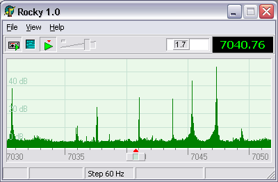
Main window
System Requirements
RF Hardware: SoftRock.
If SoftRock is not available, Rocky can be used to play back
I/Q data recordings.
Operating system: Windows Vista, Windows 7, Windows 8.x or Windows 10.
Rocky 3.7
was the last version that worked on Windows ME, Windows 2000 and Windows XP..
CPU: Pentium 4, 1GHz or higher
is recommended. I tested the program on a P4 3GHz system and on Athlon 600 MHz.
It worked on both, but the CPU load was about 40% on Athlon at the 48 kHz
sampling rate. On the Pentium, the CPU load was 7% at 48 kHz and 10% at 96 kHz.
RAM: 256 Mb.
Rocky requires about 7 Mb of memory. Add 200 Mb or so for the operating system ;-)
Sound Card: Delta-44
is what I currently use. My on-board SoundMAX also works with
Rocky, but it does not support the 96 kHz sampling rate and generates a lot more noise than Delta.
Quick Start
- Download Rocky from the
Downloads section of this web site, unzip and run Setup.exe.
Follow the on-screen instructions;
- Start Rocky and click on View / Settings in the menu.
- Select the input and output devices, and specify the sampling rate.
If you have two sound cards, select different cards for input and output. This
will allow Rocky to open the output card at a lower sampling rate and thus
save some CPU cycles.
- Click on the DSP tab and enter the exact frequency of the LO in your SoftRock.
- Click on the Start Radio button.
- Use the Windows volume control to set the
desired volume. You have to do this only once, the AGC will take care of the rest.
- Read the section below to learn the basic commands.
- If you have the RXTX version of SoftRock, see the Transmitter section
on the Advanced Topics page.
Commands
Tune
- Right/Left and Up/Down arrow keys - change the operating
frequency incrementally;
- Rotate the mouse wheel - same as above;
- Drag the spectrum/waterfall display to quickly scan the band;
- Ctrl-Click in the spectrum or waterfall display to tune at the
frequency under the mouse cursor.
Snap
- Click on or near the signal in the spectrum or waterfall display to
precisely tune at the signal;
- Ctrl-Right/Ctrl-Left and Ctrl-Up/Ctrl-Down - jump to the
next/previous signal.
Pan and Zoom
- Drag the frequency scale to pan the display without changing the
operating frequency;
- Drag the Zoom slider to zoom in and out;
- Drag the corner of the window to resize the display.
Change parameters
- PgUp/PgDn - change the tuning step between 12 Hz, 60 Hz, and 300 Hz;
- Home/End or drag the filter box - change the filter bandwidth.
How To...
Calibrate the S-Meter
To calibrate the S-meter, tune at a signal
of known strength, then Ctrl-drag the marker on the meter to the place
where it should be.
Switch the bands
The drop-down button to the right of the frequency
display allows you to select one of the pre-defined bands. For each band,
the LO frequency and I/Q balance info are stored. Run the program once, then
open Rocky.ini in a text editor and add/delete/edit the band definitions.
Install the Si570-USB driver
Download the SI570_firmware.zip file from
this web page.
The driver files are located in si570\AVR-USB-Driver folder inside the zip. Extract them into
a new directory, and connect the Si570 unit to a USB port. When prompted for
the driver location, navigate to the extracted files.
Once the driver is installed, enable the Si570 support in Rocky by ticking
the Use Si570-USB check box in the Settings dialog.
Record and play back
You can record either the input I/Q signals
or the output audio signal. The I/Q recording can be played back in Rocky.
The recordings of the output signal can be played in MS Multimedia Player.
Please enter your name, callsign and QTH in the Settings dialog. Rocky will
put these data in the comments section of your wav recordings so that other
users will see at a glance when and where the recording was made, who made
it, and what the LO frequency was. When playing an I/Q wave recording, you
can view this info by moving your mouse cursor over the playback progress
bar.
Connect an iambic paddle or a straight key
Rocky 3 has a built-in iambic keyer. The paddle must be connected to a COM
port as shown on this diagram.
The same circuit can be used for a straight key.
To switch between the iambic keyer and the straight key, open CW Console
and click on one of the radio buttons in the Input group.
Set up the transmitter
The transmit mode must be enabled in the Settings dialog, and the I/Q output
device must be selected. The device must be different from the one selected for
Audio Output.
You can switch between the RX and TX modes using the "Tx" button on the
toolbar; if Vox is selected in the button's dropdown menu, RX/TX is switched
automatically when you start/stop keying.
The Mark Frequencies Unsafe for TX option paints the specified frequency ranges
in dark red on the frequency scale.
Adjust I/Q balance in the transmitter
You must have a second receiver, e.g., your base radio, or another SoftRock,
to perform TX balancing in Rocky.
- Open the TX IQ Balance dialog.
- Note the image frequency displayed on the left panel, and tune a second
receiver at that frequency. Disable AGC in the second receiver.
- Press the Start button on the left panel. The tone signal will be
transmitted, and you should hear the image signal in the second receiver.
- Drag the Phase x 100 and Gain x 100 sliders very slowly, one tick at a
time, and find such positions of those sliders that make the image tone in
the second receiver decrease in amplitude.
- Once the x100 sliders are in their best positions, drag the x1 sliders,
again very slowly, to further null the image tone. These sliders should make
the image tone barely audible or even completely inaudible.
- Repeat steps 2 through 5 for the second calibration point (right panel).
Possible problems:
If the I and Q signals are swapped, then the image and the main signal are
also swapped. Make sure that the I/Q output signals are assigned to the
Right/Left channels of the soundcard in the same way as the I/Q input
signals, and that the Channels setting in the Settings dialog matches your
channel assignment.
If one of the I/Q output signals is missing, or there is a short circuit
between them, QSE balancing is not possible. Fix the hardware problem and
repeat the balancing procedure.
If the receiver is permanently enabled in the TX mode, you will see the main
signal and the image on the band scope. Unfortunately, this display cannot
be used for image nulling. The balance settings that minimize the image
spike on the bandscope are different from those that minimize the image in
the transmitted signal, because the TX output signal enters the receiver
through several different paths, not just through the antenna connector.
Operate Split Frequency
The RIT/XIT/Split functionality is implemented
as a single Split function that allows you to set the TX freqency
independently of the RX. A right-click on the spectrum enables split and
sets the frequency. The Split mode can be toggled by left- or right-clicking
on the split offset indicator next to the frequency display.
Set up and use Rocky in the BPSK-31 mode
The operating instructions for the BPSK-31 mode are provided in the
Bpsk31.txt file that comes with Rocky.
Version history
V.3.7
V.3.6
- Support of a paddle via Si570-AVR-USB;
- Data shift by 1 to 8 samples in the RX and TX modes.
V.3.5
V.3.4
-
Support of a straight key
V.3.3
V.3.2
-
Statistical error correction in the BPSK31 decoder
V.3.1
-
BPSK31 decoder and transmitter
V.3.0
-
CW TX mode. Requires the RXTX version of SoftRock
V.2.0
-
Binaural reception, beam forming, QRM nulling. Requires two identical
Softrocks that share a single LO. This version is no longer in development,
the executable file is available on the
Downloads page
V.1.5
-
Optional one-sample shift for compatibility with Sound Blaster Live
V.1.4
-
Waterfall display enhancements: key-click filter and super resolution mode
V.1.3
V.1.2
-
SSB mode implemented. The upper and lower cutoff frequencies of the SSB filter
are independently adjustable.
V.1.1
-
Multi-band support;
-
WAV file recording/playback
Appendix
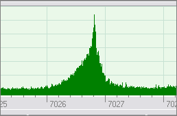
Examples of signals on the spectrum display
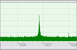
| This is a slow, well-shaped CW signal. Perhaps you could copy it visually
by watching the peak jumping up and down.
|
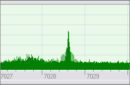
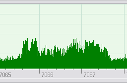
| High speed CW. The structure of the keying sidebands is clearly visible.
|
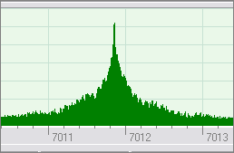
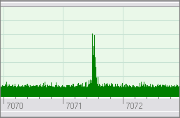
| CW with heavy key clicks.
|
| Chirping CW: the keyclick sidebands are asymmetric.
|
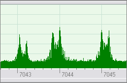
| SSB signals can be easily recognized by their 3 kHz bandwidth.
|
| An RTTY signal has two peaks that are 170 Hz apart. Three signals
are present on this screenshot.
|
| PSK31 is a phase-shift-keyed signal with the baud rate of 31.25 Hz. Its two
spectral components are only 31.25 Hz apart but still appear as two separate
peaks on the spectral display.
|
Copyright © 1998-2020 Afreet Software, Inc.

|
|
|
 Downloads
 Registration
 Author's e-mail
|
